
Tips & Tricks
Precision Practices: Lead-ins and Lead-outs
OMAX waterjet machines are designed for high-precision machining. A combination of meticulous mechanics, rigid construction, and velocity control from the software ensures the highest degree of precision in the machined parts. Even with all that precision built in, you, as the operator, are able to hone that precision further by implementing a few fundamental practices. In OMAX’s Intelli-MAX LAYOUT software, you will build lead-ins and lead-outs, as well as set their proper angle and distance, to correctly cut your designed part every time.
With lead-ins, the mixture of water and abrasive starts off cutting into the material at an optimal distance and angle away from the desired cut path. Cutting with a lead-in will let the waterjet stream pierce completely through the material prior to actually cutting the desired part path. A lead-in has three purposes:
- To give the jet a spot to turn on while stabilizing pressure and abrasive flow prior to cutting.
- To provide room for a faster linear pierce instead of a slower boring in a single spot.
- To minimize or eliminate blemishes on the surface of the final part.
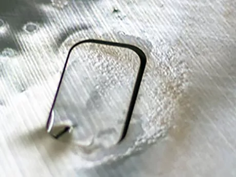
The lead-out helps prevent irregularities that result when the jetstream is turned off. Lead-outs allow enough time for the mixture of water and abrasive to cut all the way through the material leaving a precision cut piece without unintended tags or burrs.
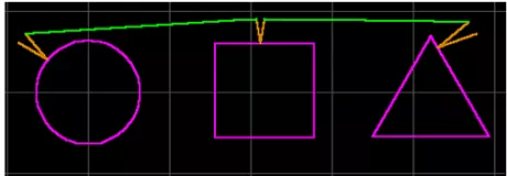
Typically, on OMAX waterjets, it is better to use “V”-shaped leads instead of “U”-shaped lead. A “V”-shaped lead-in/lead-out has two lines of a set length at an angle calculated (between type of material, its thickness, grit of abrasive, cut quality, etc.) for the specific material you are cutting. If a “U”-shaped lead is used on thicker material, the waterjet has a chance to skip into the area that has already been cut, and will leave a blemish. Placing leads at external corners of parts will almost always produce better results than placing them at other locations. Experimenting with different lead-in/lead-out types as well as their placement on the cutting path will teach operators the best options for precision cutting of their specific material.
Here are a few tips for creating your lead-ins and lead-outs:
- When piercing brittle material that may chip or crack, make the lead-in long enough that it pierces as far away from your part as possible. This way, if the material chips while piercing, your part will still be fine.
- Put lead-ins/lead-outs in spots where the quality is not important, and where blemishes can be removed easily.
- If you have an outside corner to work with, it is usually best to extend the corner into a lead. Such corner leads are much faster, due to not having to slow down when transitioning into the part. This method of lead rarely leaves any kind of blemish on the final part.
LAYOUT is equipped with a “Lead i/o” button at the bottom of the “Draw” sidebar. In addition, the “AutoPath” tool will not only create a traverse path for your project, but will fill in all lead-ins and lead-outs with the simple click of a button. The default setup for these tools is ideal for most all situations. The advanced user, though, is encouraged to experiment to see if you can do better for specific situations.
For more information on lead-ins and lead-outs, you can consult your OMAX Interactive Reference (OIR) that is available with the premium Intelli-MAX software package or check out ProtoMAX KnowledgeBase.